
A tandem gear pump — sometimes also called a double gear pump or dual gear pump — is a specialized type of positive‑displacement hydraulic pump that integrates two individual gear pump sections into a single compact unit sharing one common drive shaft.
Unlike a standard single‑section gear pump, which delivers one fluid output, a tandem gear pump provides two independent flow streams or hydraulic circuits from one mechanical drive. This makes it extremely valuable in modern hydraulic systems where multiple functions — such as steering and lifting, or simultaneous tool actuation — must run from a shared power source with predictable flow and pressure characteristics.
Basic Structure and Components
A tandem gear pump is essentially two (or more) gear pump sections integrated into a single housing and driven by a common input shaft, yet each section operates hydraulically independently. This structural arrangement enables one drive source to feed multiple hydraulic circuits at once, which is a major advantage in complex systems.
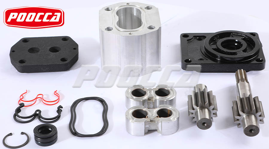
Core Components
1. Common Drive Shaft
All the pump sections — typically two in a tandem design — share a single shaft that connects directly to the prime mover (motor or engine). The synchronized rotation of this shaft drives each gear set simultaneously.
2. Gear Sets
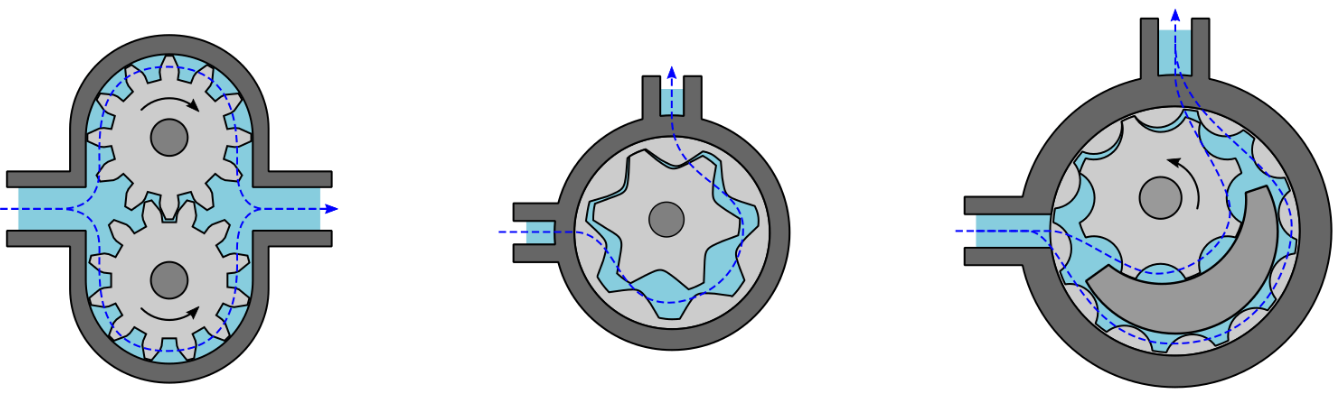
Every section contains a pair of meshing gears. These can be external or internal gear configurations depending on specific design requirements (external–external, external–internal, or internal–internal arrangements). Each gear set independently creates suction and displacement action in its respective circuit.
3. Pump Housing
The pump housing encloses all sections and maintains precise clearances between the gears and the casing walls to minimize internal leakage (“slip”). The housing also combines the suction ports (sometimes shared) and the separate discharge ports for each section.
How the Structure Differs From a Single Gear Pump
| Feature | Single Gear Pump | Tandem Gear Pump |
|---|---|---|
| Gear Sets | One pair | Two pairs (or more) |
| Flow Outputs | One | Multiple (usually two) |
| Drive | Single shaft | Single shared shaft |
| Hydraulic Circuits | One | Two independent circuits |
| System Complexity | Higher (if two pumps needed) | Lower (one pump replaces two) |
A tandem gear pump essentially doubles the functional output of a single gear pump without doubling the installation footprint or total drive power, enabling multiple flow streams with distinct flow or pressure requirements.
Operating Principle
Understanding how a tandem gear pump works begins with first recognizing that it operates on the positive displacement principle, meaning it delivers a fixed volume of fluid per revolution based on the geometry of its gears and housing. This consistency is what gives gear pumps their predictable performance in hydraulic systems.
A tandem gear pump essentially consists of two gear pump sections mounted in one housing and driven by a shared input shaft. Each section has its own pair of gears and usually its own discharge port, though the inlet side is sometimes shared.
Step‑by‑Step Working Process
1. Shaft Rotation Initiates Pumping
When the input shaft — powered by a motor or engine — begins to rotate, both gear sets begin turning simultaneously. Because they are mounted on the same shaft, there is no relative motion between the sections, and each section starts its suction and discharge cycle at the same time.
2. Fluid Suction (Intake)
As each gear set rotates, the spaces between the teeth on the inlet side open up. These expanding cavities create a low‑pressure zone (vacuum) that draws hydraulic fluid from the reservoir into the pump. This suction action happens independently for each section.
3. Trapping and Carrying Fluid
Once fluid enters, it becomes trapped between the gear teeth and the pump housing. The fluid is then carried around the outer periphery of each gear set, following the rotation direction. The tight tolerances between the gears and the housing help minimize internal leakage (slip).
4. Compression and Discharge
As the gears approach the discharge side, the spaces between the gear teeth get smaller due to the meshing action. This change in volume forces the hydraulic fluid out through the discharge port under pressure. Because both sections operate simultaneously, the pump delivers two distinct streams of fluid — one from each section.
5. Continuous, Predictable Cycle
This cycle of suction, trapping, transport, and discharge repeats continuously with every revolution of the shared shaft. Since each section has a fixed displacement per revolution, the flow rate of each output is directly proportional to shaft speed and section displacement, giving reliable and predictable system performance.
Revised Section 4: Key Performance Metrics & Data
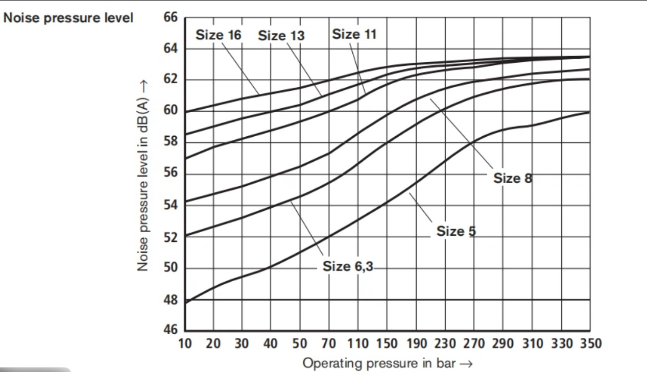
A tandem gear pump’s performance is defined by its ability to deliver stable flow and pressure while maintaining good efficiency in real operating conditions. Because gear pumps are positive‑displacement, delivered flow is roughly proportional to shaft speed and displacement, although actual flow is always less than theoretical due to internal leakage (“slip”) and fluid conditions.
Typical gear pump systems operate reliably up to nominal pressure levels around 200–300 bar for many industrial applications, with continuous operating speeds up to several thousand RPM depending on design. Volumetric efficiency — the ratio of actual flow to theoretical flow — is a key metric, often ranging above 80% in well‑built units under optimal conditions, and it varies with pressure, viscosity, and clearances.
Performance curves (flow vs. pressure and flow vs. efficiency) are essential tools for engineers, as they show how the pump will behave under specific system requirements, helping you balance flow, pressure, and energy use for your application.
Advantages & Where Tandem Pumps Shine
A tandem gear pump offers several practical advantages that make it highly desirable in many hydraulic systems, particularly where multiple circuits or differing flow/pressure needs exist.
1. Dual‑Output Flexibility
By integrating two pump sections in one housing, each with its own discharge, a tandem gear pump can supply two independent hydraulic circuits from a single drive source. This allows one section to deliver a high‑flow/low‑pressure output while the other provides a low‑flow/high‑pressure output, matching different loads without separate pumps.
2. Compact and Space‑Saving Design
Combining two gear pump sections into a single unit significantly reduces the installation footprint compared with using two independent pumps. This is especially valuable in mobile equipment and compact hydraulic power units where space is limited.
3. Simplified Drive & Plumbing
Since both sections are driven by a common shaft and often share a suction inlet, the system requires fewer couplings, hoses, and fittings. Fewer components mean less system complexity and lower potential leak points.
4. Cost Efficiency
Using one tandem pump instead of two separate pumps often reduces component cost, installation labor, and maintenance effort, yielding a more economical solution over the life of the system.
5. Broad Industrial Applicability
Tandem gear pumps are widely used in construction and earthmoving machinery, agricultural equipment, mobile hydraulic power units, and industrial automation where multi‑function hydraulic demands exist.
Common Misconceptions and Technical Clarifications
Working with tandem gear pumps can be straightforward once you understand how they actually function — but even experienced buyers and engineers sometimes hold wrong assumptions that lead to suboptimal designs or wrong pump selection. Below are the most common misconceptions and the real technical facts you should know.
Misconception 1: “Tandem gear pumps inherently produce higher pressure.”
Reality: A tandem gear pump does not multiply pressure simply because it has two sections. Each section delivers fluid up to the pump’s rated pressure based on design tolerances, material strength, and system resistance. The presence of two sections provides independent flow paths, not extra pressure.
Misconception 2: “Fixed‑displacement means no way to control flow or performance.”
Reality: Although gear pumps are fixed‑displacement devices, you can control flow by varying the driving speed (RPM) or by using external valves and control systems. Fixed displacement only means flow per revolution is constant for a given section, not that you have zero control over output.
Misconception 3: “Gear pumps are only for hydraulic oil and nothing else.”
Reality: Gear pumps are versatile and can handle a wide range of fluids — oils, polymers, resins, and more — as long as the fluid’s viscosity and cleanliness are compatible with pump design.
Misconception 4: “Tandem gear pumps always deliver exactly the same flow from each section.”
Reality: In systems with differing downstream pressures or variable loads, the effective flow from each section may vary due to control valves or pressure compensators in the circuits. The pump delivers two independent outputs, but system demand and controls determine actual delivered flow.
How to Choose the Right Tandem Gear Pump
1) Define System Requirements
• Determine required flow rate for each circuit (L/min or GPM).
• Identify maximum working pressure — the pump’s rated pressure must meet or exceed this.
• Collect fluid properties: viscosity, temperature range, chemical compatibility. These affect pump type and materials.
2) Match Pump Type and Displacement
• Choose the appropriate gear pump type (e.g., external for standard hydraulics, internal for higher viscosity or smoother flow).
• For tandem pumps, set section displacements based on individual circuit demands — equal sizes for balanced flows or different sizes for unequal flow requirements.
3) Material and Seal Selection
• Select materials and seals compatible with the fluid and environmental conditions (corrosion, temperature, abrasives).
• High‑quality sealing reduces leakage and extends pump life.
4) Suction and Operating Conditions
• Ensure suction lift and piping design support stable fluid supply; poor suction increases wear and reduces efficiency.
• Confirm the pump’s RPM range matches your drive unit to avoid cavitation or premature wear.
Conclusion & Professional Recommendation
A tandem gear pump is a highly effective solution when you need multiple hydraulic circuits powered from a single drive with predictable, positive‑displacement flow. By integrating two gear pump sections into one compact unit, tandem pumps save space, reduce plumbing complexity, and often lower total system cost compared with installing multiple separate pumps. Their design delivers steady fluid flow proportional to shaft speed, making them suitable for construction machinery, agricultural equipment, industrial power units, and mobile hydraulics.
However, it’s equally important to recognize their limitations: gear pumps — including tandem models — perform best with clean, compatible fluids and at moderate pressures; they are less adaptable to highly abrasive media, extreme pressures, or variable‑flow demands without additional controls.
At Poocca, with over two decades of experience in hydraulic systems, we’re ready to help you select, size, and configure the ideal tandem gear pump for your application — whether you need multiple outputs, space‑saving designs, or a pump optimized for your specific loads and controls. Contact our hydraulic experts for personalized guidance, technical consultation, or a custom quote tailored to your project’s demands.
Post time: Mar-26-2026


