
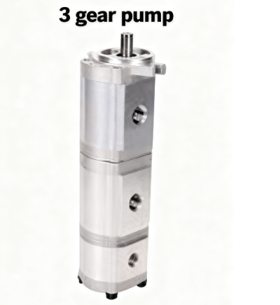
Picture this: a compact mechanical marvel tucked inside a hydraulic system. You wouldn’t see it, you wouldn’t hear it (much), but day in, day out it hums quietly, doing something remarkable — raising fluid pressure in three successive steps. This is the “3-stage hydraulic gear pump,” a behind-the-scenes powerhouse in many industrial systems.
In this article, we’re going to treat this little pump as our protagonist. We’ll explore:
-
What a 3-stage gear pump is, and how it’s different from simpler pumps
-
How fluid journeys through its three gear sets — stage by stage
-
The design trade-offs engineers wrestle with
-
Real-world uses where 3-stage versions make sense
-
Tips on selection, maintenance, and common pitfalls
Concept of Multi-Stage / 3-Stage Gear Pumps
What Does “3-Stage” Mean?
When we say “3-stage gear pump,” we’re referring to a single pump housing that contains three gear pump modules arranged in series. The hydraulic fluid passes through each stage one after another. In effect, each stage contributes to raising pressure (or overcoming system losses) progressively.
It’s like climbing a three-step staircase: you don’t jump to the top in one go; you climb step by step. Each “step” (stage) lifts the fluid a bit higher in pressure.
Sometimes multi-stage pumps are discussed more generally: “multi-stage” can mean any pump combining two or more pumping elements (in series) to boost pressure or head..A “double-stage” or “two-stage” pump is a simpler version of the same idea.
How the Stages Are Combined & How Pressure Adds
In a 3-stage arrangement, each gear section is sized and rated for certain pressure and flow. The stages are in series
If everything were ideal (no leaks, perfect efficiency), you might expect:
Pout=P1+P2+P3
where P1,P2,P3 are the pressure gains from each stage. However, in reality, internal leakage, friction, and flow losses make the sum less than ideal.
One nuance: the flow rate
Why Use Multi-Stage Instead of a Single Big Stage?
You might wonder: why not just build one monster gear pump with a huge gear set that creates the desired high pressure? Why go through the trouble of stacking three?
Here are the reasons engineers often go multi-stage:
-
Compactness & modularity: Each stage can be a smaller pump, and stacking them avoids the need for a single huge, bulky part.
-
Pressure flexibility: If you design stage 1 and 2 to operate at lower intermediate pressures and only the final stage to push to the maximum, you can optimize materials, clearances, and leakage control per stage.
-
Better control of leakage & stresses: Extreme pressure in a single stage forces very tight clearances and heavy construction; breaking it into stages relaxes each stage’s demands.
-
Easier isolation / bypass / diagnostics: In some designs, you may be able to bypass or isolate one stage (for maintenance or in abnormal conditions).
But of course, there are trade-offs. More stages mean more interfaces, more leakage paths, more sealing challenges, and a bit more complexity in design.
A Fluid’s Journey: Stage by Stage
Let’s walk through an idealized “story” of a fluid particle going through a 3-stage pump:
-
Intake & Stage 1
Fluid is drawn from the reservoir into the first gear set. The meshing of gears creates suction, drawing fluid into the gear tooth cavities. The gear rotation carries this fluid around the outer perimeter, then delivers it out to Stage 2. -
Into Stage 2
Stage 2’s inlet sees the output of Stage 1. In Stage 2, the same volume is compressed further: clearances are smaller, the fluor is squeezed more, pushing the pressure up. Then it passes onward to Stage 3. -
Final Stage (Stage 3)
The fluid enters with a moderately elevated pressure and is forced to its final target pressure here. After Stage 3, the fluid exits to the downstream hydraulic circuit.
At each stage, leakage (slip back through clearances) and friction losses subtract from the ideal pressure gain and reduce volumetric efficiency.
Internal Structure & Components
In a 3-stage hydraulic gear pump, you can think of it as three gear pump “units” packed into a single housing, sharing a common shaft and coordinated flow paths. Let’s peel back the layers and see how it’s built, piece by piece.
Overall Layout: Three Chambers in One Shell
The pump casing is typically divided into three gear chambers (Stage 1, Stage 2, Stage 3), each with its own pair of gears (or rotor/idler, depending on design). The casing also houses inter-stage channels or passages so that the output of one stage feeds into the next stage’s inlet.
You might imagine a long cylindrical shell, with partitions (walls or spacer plates) separating the stages, but with fluid passages drilled or machined to link them internally. Each stage must align precisely with the main shaft and maintain sealing to avoid large leakage between stages.
Key Components
Here are the main mechanical parts in each stage, and some “shared” parts across the entire 3-stage assembly:
| Component | Function | Special Considerations in Multi-Stage Design |
|---|---|---|
| Gear set | Moves fluid by trapping volume between gear teeth | All stages should have matched flow capacity (same displacement) unless intentionally different; gear materials and tolerances matter more at high pressure |
| Shaft / Common Drive Shaft | Drives all three gear sets | Must be rigid and precise, handle torque, support bearings, maintain alignment across stages |
| Bearings / Bushings | Support the shaft and reduce friction | More stages → more support points & design complexity to prevent misalignment or bending |
| End covers / Side plates | Seal off the sides of gear chambers and maintain precise clearances | Must be designed to withstand internal pressure and avoid distortion |
| Seals & Gaskets | Prevent leakage (axial, radial) between chambers and external environment | In a multi-stage pump, sealing is more critical because each interface is a potential leakage path |
| Inter-stage passages / Flow channels | Provide fluid path from Stage 1 → Stage 2 → Stage 3 | The geometry (smooth transitions, minimal sharp corners) matters to reduce pressure losses and avoid turbulent flow |
| Clearance & Tolerances | The small gaps between gear teeth, gear surfaces, and housing | These gaps determine internal slip (leakage) — much harder to control in multi-stage design |
| Mounting interfaces / Ports | Suction port (inlet) and final discharge port, plus any intermediate monitoring ports | Must be robust, well-sized, and positioned to avoid cavitation or excessive pressure drop |
Performance & Design Highlights
In this section, we’ll look at how a 3-stage gear pump performs in practice — but in everyday language, not engineer-speak. Think of this as the “what you should expect and watch out for” guide.
What Makes a Pump “Good” (In Simple Terms)
When someone judges a pump, here are the basic things they check:
-
How much fluid it actually moves vs. what it should move
Because of tiny leaks and internal inefficiencies, a pump never achieves its ideal output. We call the ratio of real output to ideal output the volumetric efficiency. -
How much energy is wasted by friction and internal drag
Even if fluid is moving, energy can be wasted by rubbing parts, gear meshing, bearings, etc. That’s why pumps aren’t 100 % efficient. -
How much pressure it can reliably produce
The design must withstand the internal pressures without breaking seals or deforming parts. -
How stable the inlet (suction) conditions are
If the pump isn’t getting enough fluid at its inlet—say the fluid supply or piping is bad—problems like “starving” or cavitation can occur, harming performance. -
Influence of fluid temperature / viscosity
When fluid is thin (low viscosity), leakage is worse. Too thick, and flow is harder. Temperature change affects this.
Trade-offs and What to Be Careful Of
Because a 3-stage pump has three “mini-pumps” inside, engineers must balance a few competing concerns. Here are the key trade-offs, described in simpler terms:
-
Leakage accumulates
In each of the three stages, there is some leakage (fluid slipping back). Those small leaks add up, so the more stages, the more opportunity for loss. -
Pressure losses between stages
The flow from one stage to the next travels through channels and passages. Poor design of those paths (narrow, twisty, rough) causes extra pressure drop, reducing the effective “boost” each stage gives. -
Stiffness and distortion
Under pressure, the pump’s body, covers, or internal parts can slightly bend or deform. Even small bending can alter clearances and worsen leakage. -
Thermal expansion mismatches
Parts heat up differently. If one part expands more than another, seals and clearances might get out of harmony, reducing performance or causing wear. -
Cumulative tolerances and assembly errors
Tiny misalignments or machining errors in each stage add up. If not handled carefully, these errors can degrade performance significantly.
Advantages & Challenges of 3-Stage Gear Pumps
Let’s look at what makes a 3-stage gear pump shine — and where it might trip up. Think of this as the “pros and cons” you might tell a friend who’s curious about these pumps.
Advantages (What You Gain)
-
High Output Pressure in a Compact Package
Because three pump stages are stacked in one body, you can reach higher pressures than a single gear pump without requiring a huge gear set. In other words: get more “oomph” without blowing up the size. -
Better Efficiency Through Smaller Components
Each stage can be built more moderately (rather than pushing one gear set to extremes). This allows tighter clearances and more effective operation in each stage. Multi-stage designs often help keep each component operating closer to its “sweet spot” efficiency. -
Flexibility in Stage Design
You can tailor each stage for slightly different pressure or flow behaviors. For example, earlier stages can “pre-boost” pressure, and the final stage takes over for the hardest job. -
Potential for Noise / Vibration Reduction
Because pressure is built more gradually, the mechanical stress per stage is lower. Some designs report lower noise compared to a single pump trying to reach the same pressure. -
Reliable & Durable (If Designed Well)
With proper materials, precise machining, and good sealing, 3-stage gear pumps can deliver long service life, especially in stable hydraulic systems. Many industrial “multistage pump” guides list reliability and lifespan as a key advantage.
Challenges & Trade-Offs (What to Watch Out For)
-
Cumulative Leakage / Efficiency Losses
Every stage has some internal leakage (fluid slipping back). In a 3-stage setup, these leakages add up, reducing the net output more than in a single stage. -
More Complex Internal Flow Paths
Fluid must pass through interstage channels, pipes, or passages. If those paths are poorly designed (too twisty, narrow, sharp turns), you lose pressure. -
Greater Precision Required
Because you’ve got three stages jammed into one, tolerances, alignment, and machining errors become more critical. Small misalignments in each stage can accumulate. -
Higher Cost / More Sophisticated Manufacturing
More parts, more seals, tighter machining — all these raise cost. If you’re building custom or high-volume, the economics must justify the complexity. -
Sensitivity to Fluid Quality & Wear
Contaminants, temperature swings, or wear over time can degrade clearances and worsen leakage. In a 3-stage pump, that effect is magnified since performance losses cascade. -
Limited for Fluids with Solids / Abrasives
Because tolerances are tight, pumping fluids containing solid particulates or abrasives is risky — wear will destroy precision parts faster.
Applications & Comparisons
Now that we’ve covered how 3-stage gear pumps work and what makes them tick, it’s time to see where they actually get used, and how they stack up against other pump types. This is your “where this fits in the real world” section.
Where 3-Stage Gear Pumps Shine (Typical Applications)
Here are some situations and industries where a 3-stage gear pump (or multi-stage gear pump) is a strong candidate:
-
Hydraulic power units with multiple pressure circuits
In machines that need to feed several hydraulic functions (clamping, pressing, tightening) at different pressures, a 3-stage pump can deliver a “tiered” pressure structure in one integrated unit. -
Compact high-pressure systems
When you want to reach relatively high pressure but spatial constraints (weight, envelope) don’t allow a large single pump, a multi-stage design offers a space-efficient solution. -
Industrial machinery & presses
Machines that need moderate to high force, such as metal stamping presses, injection molding, extrusion, or rolling mills, can benefit from compact, staged pressure boosting. -
Mobile or off-road hydraulic equipment
In construction, agricultural or forestry machinery, where robustness and pressure flexibility matter, multi-stage gear pumps can be used in hydraulic attachments or auxiliary circuits. -
Hydraulic test stands, lab rigs, research setups
When you want a pump with fine control over pressure rise and multiple possible pressure outputs, a 3-stage pump gives flexibility to adjust or bypass stages under different test conditions. -
Specialty OEM systems
Some equipment designers integrate multi-stage pumps directly into compact systems for custom machinery – e.g. metalworking equipment, heavy-duty industrial systems, or synchronized actuator drives.
How 3-Stage Gear Pumps Compare with Other Pump Types
To help you see where 3-stage gear pumps fit in the broader pump “ecosystem,” here’s a comparison with some common alternative types:
| Pump Type | Strengths | Weaknesses (vs. 3-Stage Gear Pump) |
|---|---|---|
| Single-stage gear pump | Simpler design, lower cost, easier to maintain | May not reach desired pressure; worse efficiency or size when pushed hard |
| Vane pump | Lower noise, smoother flow, better for moderate pressure | More complex, more sensitive to fluid quality, less suited to extremely high pressures in compact space |
| Piston (plunger) pump | Very high pressure capability, good efficiency, long life in demanding conditions | More expensive, more complex, less forgiving, bulkier for lower pressure ranges |
| Centrifugal / multistage centrifugal | Good for high flow rates, relatively simple for certain fluid types | Not good at high pressure at low flow; performance drops at high viscosity; not a positive displacement type |
| Hydraulic intensifier / booster | Can “multiply” pressure of an incoming pump fluid | Usually only for limited duty cycles or lower total flow / volume applications |
Maintenance & Troubleshooting
Maintenance Tips (Keep It Healthy)
-
Keep the fluid clean
Dirt, metal particles, water, or other contaminants are a leading cause of pump failure. Use good filters, change them regularly, and don’t allow your system to be exposed to dust or moisture. -
Monitor operating data
Keep track of pressures, flow rates, temperature, vibration, and power consumption. Sudden deviations often hint at trouble before it becomes serious. -
Inspect seals & gaskets
Seals age, crack, or lose elasticity. A small leak can grow and greatly reduce pump efficiency. Check them periodically and replace when signs of wear appear. -
Check alignment & mounting
Misalignment between pump and drive (motor, shaft, coupling) causes extra stress, vibration, and wear. Ensure the pump is firmly mounted, well aligned, and bolts are properly torque’d. -
Pre-warm / control startup
If your system starts in cold conditions or with thick fluid, allow some gradual startup or preheating so that lubrication is established before full load. -
Scheduled inspection / teardown
At planned intervals, open up the pump and check gear surfaces, bearing wear, clearances, and internal passages for signs of damage or wear.
Troubleshooting: Common Problems & Fixes
Here are common faults you might run into, along with possible causes and remedies. Think of this as a “checklist for diagnostics.”
| Problem / Symptom | Possible Cause(s) | What to Do / Remedy |
|---|---|---|
| Low flow / not reaching pressure | Excess internal leakage (clearances too large), worn gears, damaged seals, blocked passages, wrong fluid viscosity | Inspect for mechanical wear, replace seals, clean passages, check fluid spec, measure clearances |
| Unusual noise / whining / vibration | Cavitation (due to bad suction), air in system, misalignment, worn bearings | Check suction supply & lines, bleed air, realign pump, inspect bearings |
| Overheating | Excess friction, internal leakage turning energy to heat, poor cooling, high viscosity fluid | Reduce load, improve cooling, check for worn parts, ensure fluid is correct |
| Leakage (external or between stages) | Damaged seals, cracked housing, loose bolts, poor seal surfaces | Replace or reseat seals, fix cracks if possible, retighten connections |
| Sudden stoppage / pump fails completely | Power supply failure, drive coupling failure, internal seizure, pressure relief valve stuck | Check electrical supply, inspect coupling, disassemble pump, test relief valve |
Conclusion & Product Showcase
Let’s wrap up what we’ve learned and give you a few product / brand ideas you can use or drop into your blog.
Key Takeaways
-
A 3-stage hydraulic gear pump is essentially three gear pump modules in series, chained to boost fluid pressure step by step.
-
Its advantage lies in delivering higher pressure in a relatively compact and integrated design, with flexibility to distribute “pressure burden” across stages.
-
But that benefit comes with challenges: cumulative leakage, flow losses between stages, precision machining demands, and sensitivity to wear and seal integrity.
-
In real systems, good maintenance, fluid cleanliness, and smart design (balanced stages, robust structure) make the difference between a pump that lives and one that dies early.
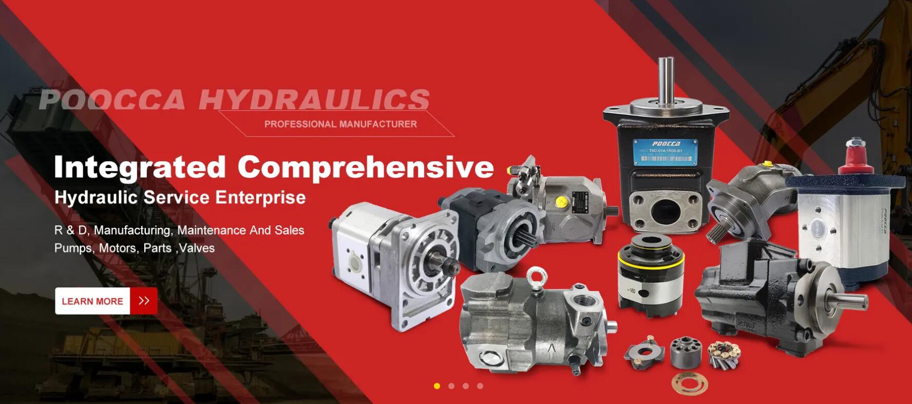
Why Consider Poocca?
If you’re looking to recommend or source quality hydraulic pumps, Poocca Hydraulic (Shenzhen) Co., Ltd. is a noteworthy choice. Here’s why:
-
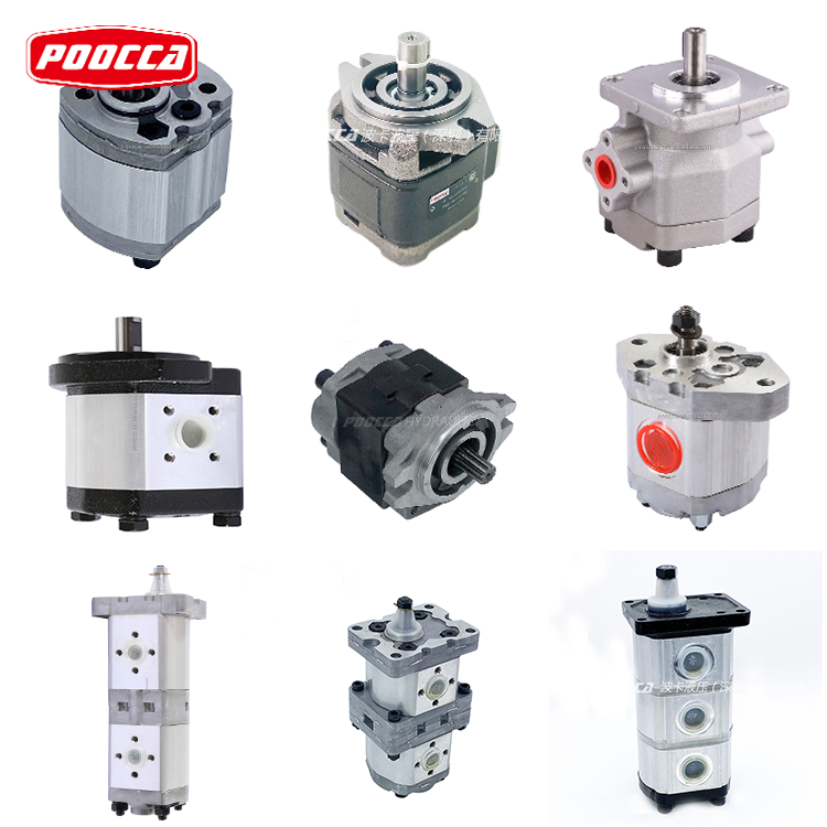
Broad product range & model availability
They make gear pumps, piston pumps, vane pumps, motors, valves and related hydraulic components. -
Strong quality control & certification
Their factory operates multiple inspection steps per unit, and they claim to have ISO / TS / QC systems in place. -
Inventory & quick assembly
According to their product pages, Poocca maintains large stocks of parts so that when you place an order, assembly and shipment can happen quickly. -
International reach & brand cooperation
They partner with international hydraulic brands and export to many countries. -
Model variety & customization
They offer external gear pump series (AZPFF, AZPGG, AZPF etc.) with various displacements and pressure ratings.
Here are a few highlights:
-
ATO 10/20/25/30 GPM Multi‑Stage Gear Pump — useful to compare a higher flow, multi-section pump in your blog discussion.
-
GP‑F20 High‑Pressure Gear Pump — shows what a robust, high-pressure gear pump looks like.
-
Muncie PK Series Gear Pump — a well-known brand in hydraulics, good reference point.
-
Others (SAE AA, Concentric, etc.) help illustrate how size, displacement, pressure trade off.
FAQ
-
What is a 3-stage gear pump?
It’s a single hydraulic pump built with three gear-pump stages in series, so fluid is pressurized in three steps. -
Does the output pressure just equal the sum of all three stages?
Ideally yes, but in reality internal leakage and losses reduce the total, so the real output is a bit less. -
Why does the pump run but deliver no flow?
Common causes include air entering the suction line, wrong rotation direction, worn clearances, or clogged passages. -
What causes noise, overheating, or reduced performance?Cavitation (poor inlet), fluid contamination, misalignment, poor lubrication, or excessive wear are frequent culprits.
-
How often should I inspect and maintain the pump?
Regularly — check fluid cleanliness, seal condition, alignment, temperature data. Do periodic internal inspection and replace worn parts before failure.
Post time: Oct-18-2025


